
Materials and mechanical testing
Evidence of how materials, joints and repairs behave under load, over time and in their environment.
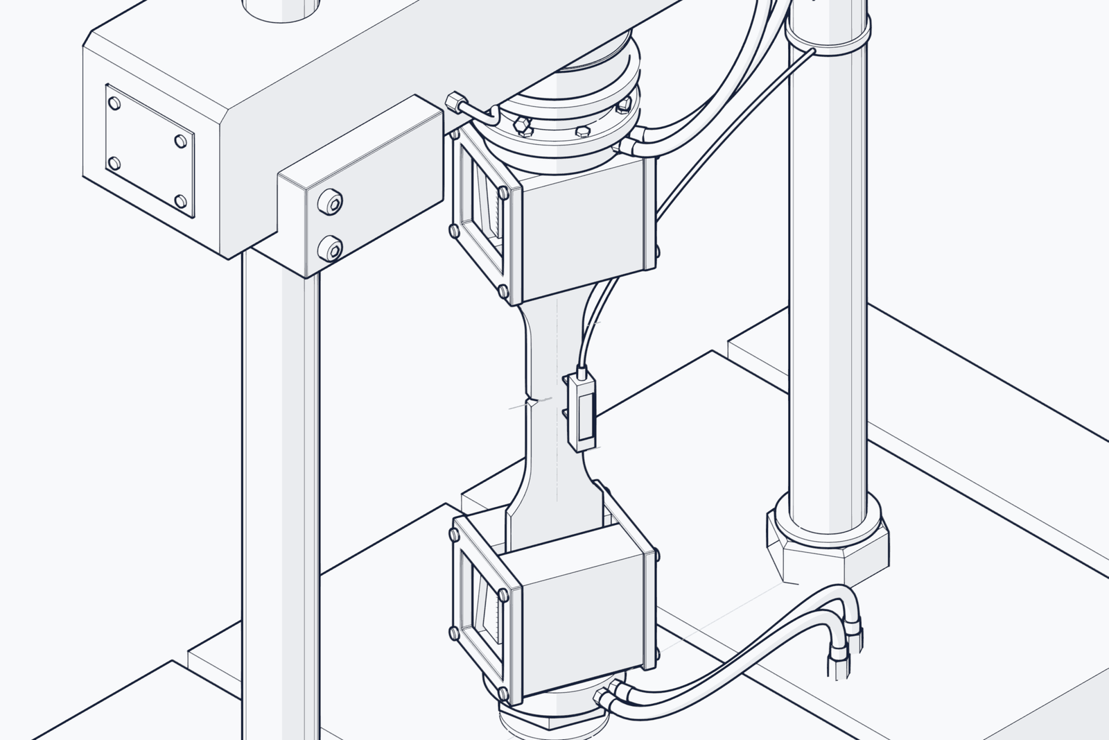
Some questions can only be answered by loading a specimen until it changes. Will this laminate keep its strength after impact and moisture? Will this bonded repair carry load for the rest of the part's life? Why did this component crack in service? We design test programmes around the failure mode that matters, run static, fatigue and environmental tests, and characterise materials before and after. The output supports material selection, repair substantiation, life extension and corrective action. Materials and mechanical testing is one of the areas we work in, and test programmes here often support design and prototyping projects.
Composites and bonded repairs
Composites fail differently from metals: an impact can leave a barely visible mark while delaminating plies beneath it, and a bonded repair can look sound and still carry a weak or partial bond. We inspect carbon-fibre and fibre-metal laminates for delamination, porosity and cracking; honeycomb and sandwich structures for disbonds, core crushing, water ingress and foreign objects; and bonded repairs for bond-line integrity and coverage. Natural-fibre, hybrid and metal-matrix composites are characterised before relying on carbon-fibre methods. Active thermography screens large areas but is near-surface and sensitive to surface finish; ultrasound confirms and sizes deeper defects but needs coupling. Mechanical test on representative specimens links indications to strength. You receive damage maps and sizing, repair evaluation reports, linked mechanical test results and recommendations. Equipment: infrared cameras; ultrasonic and eddy current equipment; load frames, environmental chambers and microscopy.
Mechanical and fatigue testing
A test result is only as useful as the question it was designed to answer: too few specimens leave scatter unknown, and the wrong geometry, load spectrum or environment produces a number that does not apply to the real part. Fatigue is sensitive to surface finish, joint detail, temperature and moisture. We run tension, compression, shear and flexure tests that report failure mode, not only failure load; constant-amplitude and spectrum fatigue tests, paused for inspection to track damage growth; environmental conditioning for temperature, humidity and fluids; and bolted, riveted, bonded and hybrid joint tests. Specimen numbers follow the scatter expected and the confidence the decision needs. You receive a test plan and specimen drawings, raw and reduced data, failure mode classification, statistical analysis of scatter and recommendations. Equipment: load frames, fatigue rigs, environmental chambers; instrumentation and data acquisition.
Materials characterisation and failure analysis
When a part fails in service, the obvious answer is often incomplete: a fatigue crack may start at a corrosion pit, a machining mark or a material defect, and replacing the part without finding why invites the same failure again. We examine fracture surfaces to identify the mechanism, such as fatigue, overload, stress corrosion or creep, and locate the origin; characterise microstructure, composition and coatings against specification; and assess corrosion and environmental degradation. Investigations start non-destructively, then move to optical and electron microscopy and supporting tests, because destructive steps cannot be undone. We separate contributing factors from the primary cause. You receive an investigation report with mechanism and root cause, fractographic and microstructural images, characterisation results, chain-of-custody records and ranked recommendations to prevent recurrence. Equipment: microscopy, environmental chambers, load frames; infrared cameras; ultrasonic and eddy current equipment.
How we assure the result
We test what the part will actually see in service, and when a part fails, we work back from the fracture surface to the cause. Root cause sits at the intersection of material, manufacture, load and environment, and evidence for each must be read from the failed part before it is cleaned, cut or lost; environmental chambers reproduce suspected service conditions. That means representative specimens, realistic load spectra, and environmental exposure such as moisture, temperature and fluids where they change the result. We inspect specimens before, during and after testing, so damage onset and growth are recorded rather than inferred from the final failure alone. Results come with the test conditions and scatter stated, so they can be used directly in design and life calculations. Every programme follows the same five checks.
- Method review: techniques and test plans are matched to material, lay-up, defect and decision (sandwich structures attenuate some methods strongly, which shapes technique choice), and an investigation plan sets the order of non-destructive and destructive steps.
- Calibration: inspection methods are set up on reference panels with known defects; load cells, extensometers, chambers and microscopy are calibrated and their records kept.
- Verification against known cases: indications are confirmed by sectioning or microscopy where specimens allow, reference specimens with established properties are tested alongside, and findings are compared with reference fracture features and material data.
- Review rounds: indications and sizing, data reduction, failure classification and the evidence for any stated root cause are checked in multiple rounds before anything is reported.
- Traceable records: specimen identity, conditioning, settings, test data and fracture images are linked, with chain of custody recorded for every sample.